Modelling And Visualisation Of Drilling
A Horizontal Well
Let us recall that in academic and engineering contexts, a model is a construct which encapsulates the essential features of a system of interest in a way that offers advantages over direct observation of the behaviour of the system of interest itself.
For example, an aircraft designer may construct scale models of a proposed aircraft for study in a wind tunnel. The advantages are numerous:
- Many different iterations of a model may be manufactured at a tiny fraction of the cost of a full scale prototype, the design of each iteration perhaps being informed by the performance of its predecessor.
- It is necessary only that a model encapsulates those features under investigation. Therefore, our wind tunnel model maker need only concern himself with shape. Complications like strength, longevity, power and control systems need not concern him, further simplifying the construction of the model.
- The model may be pushed beyond normal performance limits, to investigate behaviour under conditions of stall, spin, and flutter in a way that would be prohibitively hazardous in a full scale, human piloted prototype.
- By injecting smoke into the airstream upwind of the model, the flow of air over the shape of the model may be visualised in ways simply not possible on a full scale prototype.
To reap these advantages, it is essential that the model accurately represents the behaviour of the system of interest; and a great deal of the effort involved in constructing a representative model is expended in demonstrating that the model provides a true representation of the real world phemomena being investigated.
Like generations before him, my eight year old son spends a great deal of time ‘researching’ novel aerodynamic forms based on models constructed from folded sheets of A4 paper. Some of his models are encouragingly performant, but until materials technology has developed to the point where a wing’s thickness may be 1/2000th of its span, his models will not be considered truly representative of shapes that are capable of being manufactured in full scale using state of the art technology.
Above we describe a physical model. At the other end of the spectrum, a computational model may be constructed which accurately predicts the resultant forces on a wing of a given geometry in a particular airflow. Nowadays these models are highly sophisticated and robustly validated. A practical result of this sophistication is the commercial flight simulator. Twenty years ago, Airline Transport Pilots routinely honed their skills by switching the autopilot off and hand flying the aircraft during revenue flights. Today’s flight simulators are claimed to provide such high fidelity replication of the piloting experience that pilots are encouraged, and in some airlines mandated, to keep the autopilot on during revenue flights, and prepare for the unlikely event of an autopilot failure by hand flying the simulator during programmed training sessions.
We saw above how modelling may enable visualisation of phemomena of interest in ways impossible in a real world system. Let’s consider this in the context of a wellbore. A hole in the ground a few inches in diameter and maybe more than 10,000 ft deep. Imagine it’s a horizontal well, and the end of the wellbore is displaced 3000 ft from us horizontally. It’s a hostile environment down there. Temperatures can exceed 150° C, pressures tens of thousands of PSI, and if we’re drilling, anything down the hole is going to be experiencing percussive forces that can split rock.
It’s actually very difficult to observe directly what is going on at the bottom of the hole. Using sufficiently robust electronic sensors we may make measurements of temperature and pressure. With increasing sophistication we can add survey measurements, forces and vibration.
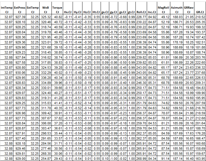
Here’s an example of 30 second’s worth of downhole measurements made by a CTD BHA.
Author: Richard Stevens
Published: 29th November 2017


Comments
Figure 1. 3D Graphical Model
Comment
Your Email
Enter your comment here:
Enter Your Comment
Your Email
Doubtless very interesting, and a considerable technical achievement, yet to a human reader, hugely impenetrable. What we really need is a model to help us understand what it means.
Here is a 3D graphical model constructed by using a minimum curvature function to join the survey measurements logged as the BHA was pulled out of the well.

Unquestionably, using a graphical 3D model makes the data immeasurably easier to understand.
We are at a fortunate time in history. Digital computers become more powerful, yet cheaper with each passing year. Computations which could only be dreamed of 20 years ago are now a reality on run of the mill desktop computers.
We are approaching the point where our wellbore model will encapsulate not only geometry, tubing forces and hydraulics, but also the mechanical interaction between the BHA, bit and formation, borehole stability and reservoir productivity.
In a direct parallel of the flight simulator, it will be possible to drill the well, virtually, in the office, encounter and resolve problems, optimise steering and wellbore placement and simulate hydrocarbon recovery, all before any equipment leaves the yard.


+44 1392 933 100 | +1 800-868-1562