Understanding Coiled Tubing Fatigue Damage And Its Influencing Factors
Author: Marat Seitimov
Published: 12th June 2019


Comment
Your Email
Enter your comment here:
Enter Your Comment
Your Email
Comments
Coiled Tubing (CT) has been widely used for well intervention, servicing and drilling. It has become widely used due to its low cost, fast mobilization, and high efficiency. The CT unit’s major consumable is coiled-tubing pipe, which is rolled onto the reel (drum). The tubing moves from the reel over the tubing-guide arch, called a gooseneck, repeatedly during operation and is usually under constant internal pressure loading. This leads to the fatigue damage of the tube; therefore, it is very important to keep track of the most fatigued zones to prevent any pipe fractures during operations that could result in tubing and BHA loss. We must note that the fatigue factor in the life of CT is unavoidable, and currently cannot be measured non-destructively. Foremost, to reduce the likelihood of coiled tubing string failures and improve reliability of the operations, it is critical to understand the mechanisms of the CT fatigue damage occurrence, and how to predict string fatigue condition.
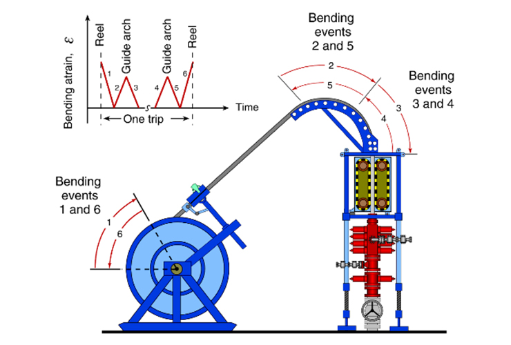
There are three major classes that identify fatigue. They are: High-cycle fatigue, low-cycle fatigue, and ultra-low cycle fatigue. Coiled tubing fatigue falls into the last category ULCF. Another example is a paper clip that fails after a few bending cycles. As seen from Fig. 1, there are a total of three bending and straightening events, which are repeated in reverse as the tubing is going down the well or out of the well (in the oilfield it is commonly described as a “trip”), resulting in a total of six bending events. Research has found that this segment of the tubing will have a higher amount of fatigue damage accumulation. Failure of the CT caused by repeated bending on the reel and over the gooseneck has been a major concern for coiled tubing service companies and operators that use their services.
It should be noted that the number of trips that coiled tubing string experiences over its entire length is not homogeneous. During routine CT well-intervention and drilling operations, the tubing string is periodically stopped and reversed in motion, therefore, certain segments of the pipe experience a higher number of trips allocated compared to the remainder of the coiled tubing string. The majority of metal fatigue occurs on the reel and at the the gooseneck prior to going into the well.
Image Source: Petrowiki.org
For many years there have been multiple studies made to measure fatigue damage using different models. A study made by Newman and Newburn, found that decreasing the coiled tubing (CT) diameter or increasing the bending radius leads to an increase of the CT life.* Another study found that increasing the wall thickness and yield strength will lead to the increase of the CT life. There were other experiments and models that measured different factors on coiled tubing life. Most of those studies are too complex to describe here. Major parameters that affect coiled tubing fatigue life are CT outside diameter, wall thickness, bending radius, operating conditions, and tubing material specifications and properties.
There are other factors that should be included in the analysis of the CT fatigue damage, such as tubing ovality, pre-bending, corrosion, mechanical damage, severe operating conditions of coiled tubing inside a well, and rotation. However, these are secondary factors compared with those described above.
*Conference Paper DOI: 10.1115/IMECE2016-65972.
Fig. 1 - Fatigue Stress Zones


+44 1392 933 100 | +1 800-868-1562