Underbalanced Offshore Coiled Tubing Drilling Case Study: Part Two
In Part 1 of this blog, we looked at the first steps you need to take when planning an offshore UBCTD project, which generally focused on understanding the reservoir. With a preliminary trajectory planned and the well pressures defined, the mechanical aspects of the coiled tubing drilling operation can now be designed.
Author: Guest Blog by Steve Nas
Published: 21st November 2018


Comment
Your Email
Enter your comment here:
Enter Your Comment
Your Email
Comments
We now know the hole size and the length of the well to be drilled, therefore we can move on to calculating the coil OD, ID and taper.
Using coiled tubing modelling software, the forces at each stage of a coiled tubing operation are calculated and analysed. These include weight-on-bit (WOB), overpull, injector requirements, drag and buckling. We know that friction factors can increase significantly when drilling underbalanced, so ensure friction factors used are well documented at this stage. Do the calculations, then double the friction factors and understand what happens to weights and pulling forces. Look at the buckling of the coil. The OD of the coil is probably fixed but the ID can be adjusted to ensure all the forces work for the well being drilled.
The length of coil and its OD and ID will determine the weight of the coiled tubing, and this is an important aspect. The total length of the coil and its OD and ID will determine the weight of the reel. The coiled tubing reel will have to be lifted onto the platform and one of the first questions to be answered is “can the coil reel be lifted onto the platform and where on the platform will it be placed?”, so this needs to be addressed early on. The platform crane needs to lift the reel from the supply vessel and place it where the platform beams can support the weight.
With the coil size and wall thickness determined, it is now time to look at the bottom hole assembly (BHA) requirements for the job. An advantage of coiled tubing drilling is that having the wireline installed inside the coil means high-speed bi-directional data transmission is possible. This provides a lot of valuable information that can be used to optimize the drilling process, something that jointed pipe operations can only dream of.
Above the bit, two float valves are installed to ensure there are no fluids flowing back up the coil. Above the motor will be an orienter tool which allows the directional control and it allows steering of the BHA. Above the orienter, the data acquisition systems are installed such as PWD, Accelerometers, Gamma Ray, Resistivity, Temperature and any other measurements required. The final piece of the puzzle will be the connection between the bottom hole assembly and the coil itself.
Designing the coiled tubing set-up
BHA requirements
Hydraulics and fluid selection
Fundamentally, to drill underbalanced, the pressure in the wellbore needs to be lower than the pressure in the formation (reservoir). As we discussed in part 1 of this blog, it is therefore critical that the reservoir pressure is known. A target pressure will be formulated, which is normally approximately 250 psi below the reservoir pressure. This safety margin allows pressure adjustments to be made when drilling. With the reservoir pressure and the required drawdown pressure known, a required fluid density can now be calculated using the TVD of the well. This fluid density will be the first indication of what kind of drilling fluid is required.
In a depleted oil reservoir, using the reservoir crude as the drilling fluid is a generally good start. There is plenty of degassed reservoir oil available from the production system and with gas injection, an underbalanced status can generally be obtained. The first objective for the fluid design is to ensure that your well will be underbalanced in a static and circulating mode with a given fluid. This ensures that there will be inflow from the reservoir when the bit reaches it.
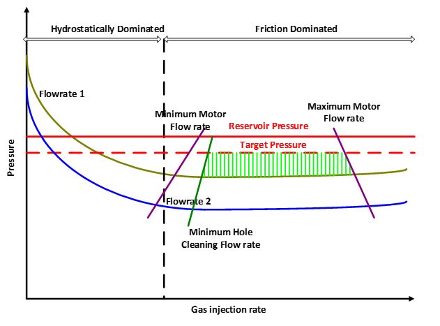
To ensure an underbalanced status can be achieved, calculations will be completed using multiphase software. The first calculations performed to ensure pressures in the well bore are underbalanced are injection rates vs gas injection and reservoir pressure. The operating window chart provides the operational parameters used to drill the well. A series of six calculations and graphs are generally designed, these are:
1. Bottom hole pressure vs liquid pump rate with gas injection (if required)
This calculation shows the pressures when drilling underbalanced and ensures the well is underbalanced when circulating. The graph also shows the amount of gas required to remain underbalanced.
2. Equivalent liquid flow rates through the BHA and bit
This calculation uses both the gas and liquid injection rates to calculate the pressures within the BHA. It calculates an equivalent liquid flow rate and is used to ensure the down hole motor has the required volume to operate, and that the operating window remains within the motor limits.
3. Annular velocity
The annular velocity is plotted to ensure hole cleaning can be achieved. It needs to be looked at in the open hole as well as in potential cased sections of the well. Annular velocities in a 7” or 9-5/8” casing may be too low to bring solids out, especially with coil in the well, so careful analysis of hole cleaning is required.
4. Annular friction pressure
The annular friction pressures are calculated as these play a significant role in UBD operations. The back pressure maintained on the choke manifold controls the bottom hole pressure and the reservoir fluid flow into the well. To ensure the well remains underbalanced, all the factors which determine the bottom hole pressure need to be understood.
Bottom hole pressure = hydrostatic pressure + annular friction pressure + applied surface pressure
5. Annular liquid volume
If both fluid and gas are injected during drilling, it is essential to understand how much liquid and how much gas is in the annulus. If pumping needs to be stopped at any time, the liquid will drop to the bottom of the well, whilst the gas rises to the top of the well. Whether or not the well will remain underbalanced with the pumps off needs to be understood, as it is possible that fluid would need to be removed prior to pumps stopping.
6. Circulating pressure
The last of the calculations, this predicts surface injection pressures and is important for selection of pumps and gas compression equipment as well as for fatigue of the coil. The injection pressures in coiled tubing are generally high and both fluid pumps and gas injection equipment need to be sized to ensure required pump pressures are available.
Bottom hole pressure versus liquid and gas injection rates
With all this analysis completed, we can start looking at the reservoir flow when the well is underbalanced. As we lower the pressure in the well, the reservoir starts to flow oil and gas into the well. This flow adds friction and velocity to the annulus, which influences wellbore pressures. During the planning stage, a lot of scenarios are reviewed to see what happens if there is a gas zone, a water zone and a high producing oil zone in the well, and what the disruptions to the system are. If there is a zone with high permeability in the reservoir, the potential exists to have a high reservoir inflow and this needs to be understood. It may not be possible to drill underbalanced past the high inflow zone because of high fluid rates and associated frictional pressures exceeding the bottom hole pressures.
Once operations start, flow modelling will need to be carried out on site to ensure the reservoir inflow performance can be measured. Flow rates of gas, oil and water at surface are measured and correlated to depth to measure the reservoir performance.
To be continued . . .


+44 1392 933 100 | +1 800-868-1562